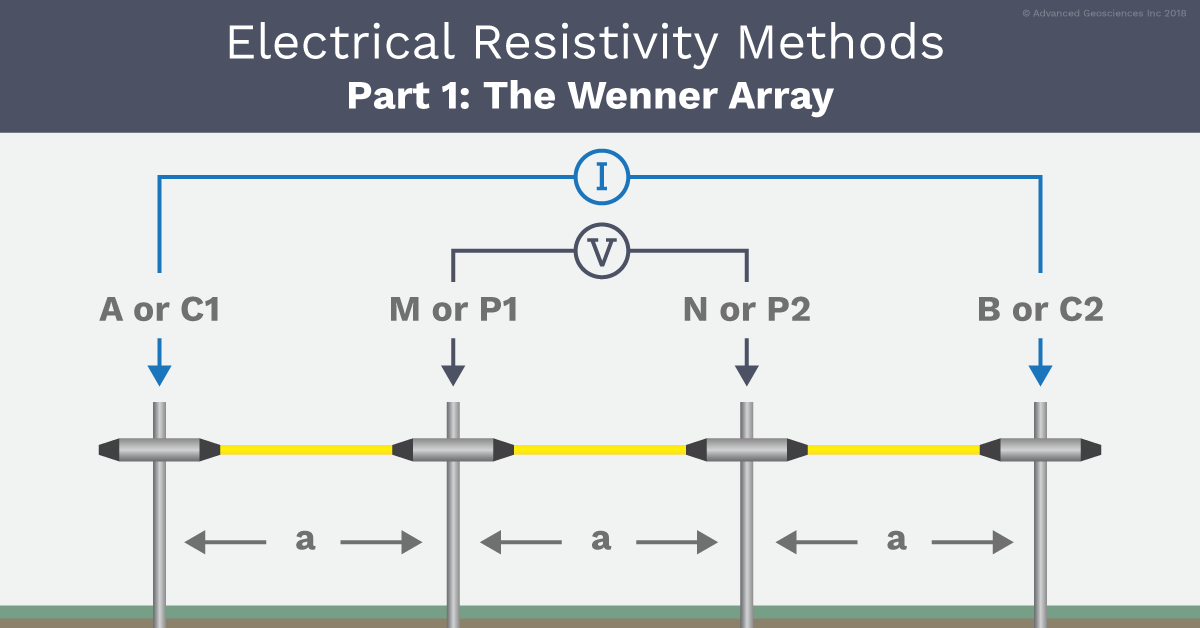
Electrode arrays are different arrangements of electrodes used to perform geophysical resistivity measurements. Electrode arrays were developed in order to make field measurements more efficient and data interpretation easier. In this series, we’ll explore 11 electrode arrays. The first array we’ll discuss is the Wenner array.
What is the Wenner array?
The Wenner electrode array is the simplest of arrays; in it, the four electrodes—A, M, N, and B—are placed in line and spaced equidistant from each other. The two outer electrodes, A and B, are current electrodes, and the two inner electrodes, M and N, are potential electrodes. With the Wenner array, the resistivity of subsurface layers is found by increasing the distance between the electrodes while maintaining the location of the center point of the array. This method is called vertical electrical sounding (VES) or electrical drilling. Detection of horizontal changes of resistivity is achieved by moving the four electrodes across the surface while maintaining constant electrode separation. This method is called profiling or sometimes electrical trenching. (Source)

Background
The Wenner array was invented in 1915 by American physicist Frank Wenner (1873-1954), who worked at the American Bureau of Standards. His development of a four-terminal bridge design consisting of two outer current injection electrodes and two inner potential electrodes equally spaced became known as the “Wenner array.”
Applications, Benefits, & Considerations Of The Wenner Array
The Wenner array is commonly used in profiling for lateral exploration of the ground, like soil testing and sometimes VES for vertical exploration of the ground, like defining horizontal layers. The logistic advantage of using the Wenner array when profiling is you only have to move four electrodes for each new measurement along the line.
The Wenner array is at a disadvantage when performing VES surveys. Since you will have to move all four electrodes for each new measurement, this means a lot of walking when the electrode spacing becomes large. For example, to move all four electrodes from 50-meter electrode spacing to 100-meter electrode spacing, one person must walk a total of 600 meters for one measurement only—and a typical VES survey may comprise around 15 measurements. The alternative is to use more people; for example, one person at each electrode plus the instrument operator.
The Wenner electrode array is used for profiling or mapping in soil testing because of an old standardised test, specified in ASTM G57, written for electrical soil testing. This standard specifies profiling and is performed with the Wenner array. With today's technology it would probably be better, based on the result and cost, to perform automatic electrical resistivity imaging surveys instead of the standardised ASTM G57 surveys.
For VES in general, the Schlumberger electrode array is at advantage, since, for most measurements, only the outer electrodes A and B needs to be moved; therefore, a crew of three people is normally enough for VES, since the instrument operator typically moves the inner electrodes the few times they need to be moved.
Although the Wenner array is still used, it is considered an outdated way to perform DC resistivity surveys. Why? Because in America, engineers employ the ASTM G57 Soil Test, also known as the four-pin Wenner method, as the standard for cathodic protection and grounding of electrical networks. This soil test is the industry standard despite being a less efficient method, and as long as it is a standard it will continue to be used.
However, it is possible to get a picture of the subsurface in terms of resistivity for finding the best groundbed location using methods like electrical resistivity imaging (ERI). The ERI method uses the same measurement but in significantly more automated locations (geometries) to extend the method of the ASTM G57 test. It produces a more accurate and complete solution for the same amount of field effort and cost. The ASTM G57 Soil Test is like making a spot measurement, while the ERI method scans a complete picture of the subsurface in terms of resistivity.
Resources & Related Information
-
In-Depth Descriptions Of 3 Soil Resistivity Testing Techniques
-
1D Geophysical Resistivity Survey: Vertical Electrical Sounding
Questions about the Wenner array?
We’ll be happy to respond to any comments or questions you have about the Wenner electrode array or any other arrays. Simply fill out the form on this page, and we’ll be in touch.

