Hello again, and welcome back to our 11-part series discussing electrode arrays. We’re deep into the non-standard electrode arrays now. This time, we’re discussing the Azimuthal Electrode Array configuration.
In case this is your first time, we’ve also covered the following:
Part 2: The Schlumberger Array
Part 3: The Dipole-Dipole Array
A quick refresher on electrode arrays (in less than 30 words):
Electrode arrays are different arrangements of electrodes used to perform geophysical resistivity measurements. Electrode arrays were developed in order to make field measurements more efficient and data interpretation easier.
What is the Azimuthal Method?
You may have noticed that we said “method” and not “array” at the beginning of this section. That’s because the Azimuthal Method is less of an array and more of an electrode orientation or method—similar to vertical electrical sounding (VES), profiling, or Mise-a-la-Masse (which we’ll get to in a later post).
“Azimuth”—in relation to a geophysical survey—is the direction or angle of a particular location compared to north. You can measure azimuth with many different electrode arrays—the Wenner Array being one of them.
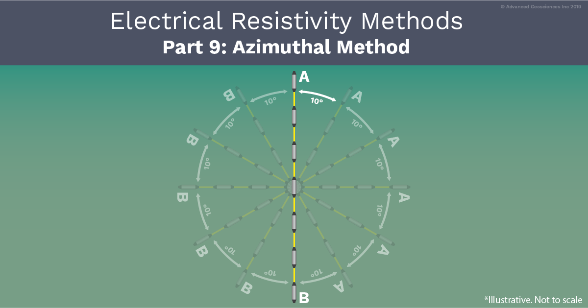
With the Wenner Array—an axial array—you set your current electrodes along the 12 o’clock and 6 o’clock and your inner electrodes on that line at a 10-meter electrode spacing. You then move your electrodes clockwise either 10 degrees or a quarter turn (depending on your preference) and take another reading. As you repeat this, your outer electrodes form a circle with a 30-meter diameter, and your inner electrodes form another circle with a 10-meter diameter. You can increase the Wenner electrode spacing to measure deeper.
Evaluation of this data gives you information about fracture patterns. The Wenner “a spacing” is associated with resistivity at different depth levels in the formation below, which is interpreted through what’s called a polar diagram or rose diagrams. This diagram uses concentric circles (which represent resistivity value) and a north, south, east, and west axis. If anisotropy is present in the ground, then the polar diagram forms an ellipsoid figure when a line is drawn from each data point, as seen in the image below:

Note: All types of Azimuthal Methods are 1D.
Benefits, Considerations, and Applications, Of The Azimuthal Method
Benefits: Consider an electrode array rotating around a center point. If there are fractures in the subsurface, at some point the electrode array will be parallel to the fractures. This happens because the fractures hold sediment, soil, clay, and moisture, which creates a more conductive path then the surrounding material. These fractures are termed heterogeneous features. Anisotropy is another directional component found in some soils which can have an azimuthal response as well. Differentiating these two features requires core samples in many cases.
Considerations: The Azimuthal Method may exhibit a response which looks like fractures, but in fact be due to a layer called a dipping bed. This is a flat layer of lower resistivity material which angles down away from the surface. This is because the Azimuthal Method is a 1D VES or sounding method and thus cannot image the true shape of the bed or fracture like a 3D image would. 3D imaging is the most reliable way to measure fractures. Multiple parallel 2D lines can also be merged into a good 3D model for this same goal. (By the way, we’ve written another article that compares 1D, 2D, and 3D surveys).
As previously noted, the Wenner Array isn’t the only array used with the Azimuthal Method—and it can actually be prone to issues. There are some who suggest that the Square Array is more appropriate for azimuthal measurements, as it is the most sensitive for direction.
Applications: Hydrogeologists can learn a great deal by applying this method to study fracture patterns and how water flows through them. Rock formations in the earth are anisotropic—meaning they have different resistivities based on the direction of the resistivity measurement. The changes in directional resistivity are often due to the fracture patterns in the subsurface.
So, for example, if a hazardous liquid is spilled, it may be critical to know the direction of the fractures in a particular area to contain the site—and electrical resistivity testing allows for a noninvasive way to “see” these fractures.
